Abstract
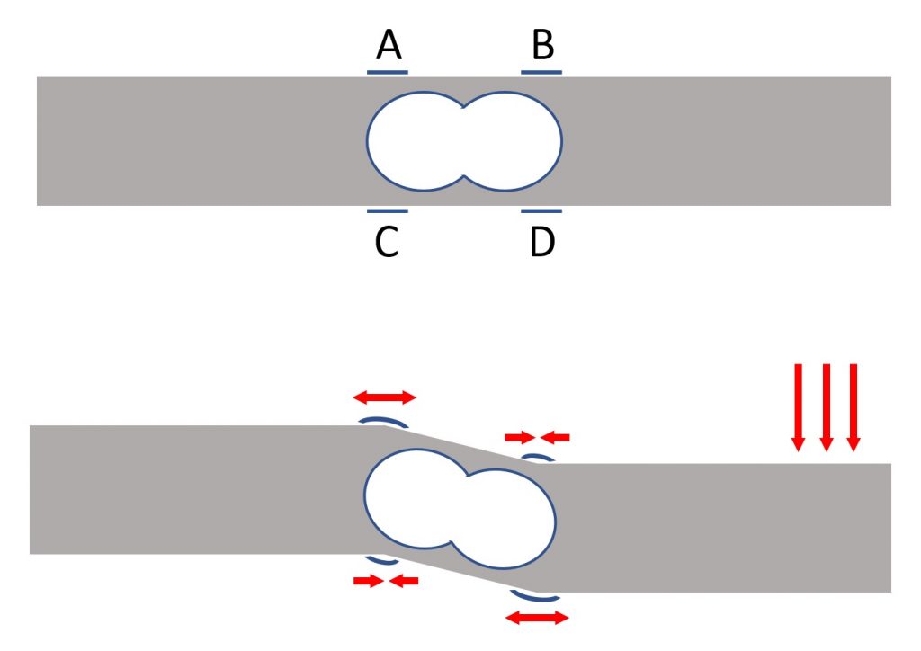
Load cells leverage the property of some materials that change their electrical resistance when subjected to compression and traction which determine their elastic deformation. The most common load cells available on the market have the shape of a metal bar with holes drilled in the central part to facilitate deformation (Figure 1).

In their typical use, the cells are blocked at one end and the weight applied to the opposite end. Strain gauges are inserted in the center of the bar, on the upper and lower faces with respect to the holes, which can be assimilated to resistive elements that change their electrical characteristics according to the level of deformation (extension or compression) to which they are subjected (Figure 2).
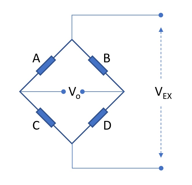
These elements are linked together to form a Wheatstone bridge (Figure 3). The bridge is excited with an input voltage (Vex), and is able to generate an electrical output signal (Vo) proportional to the imbalance of resistive value between the elements A-C and B-D. At rest all the elements have the same resistive value, the bridge is balanced and the output voltage is zero. Under load the values of the resistances change and consequently the value of the output voltage is proportional to the applied load.
To adequately sample the electrical output signal, the integrated circuit already set up for this type of application can be used. This is the HX711 (ref. [1]) whose block diagram is shown below:
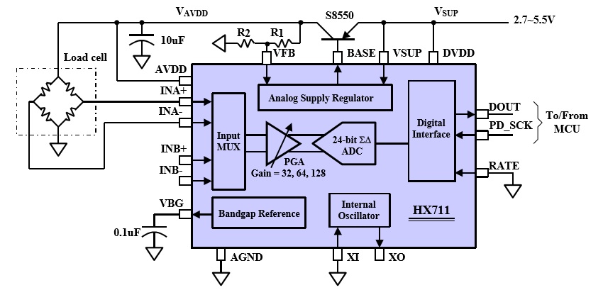
The electrical output signal of the load cell (Wheatstone bridge) is sent to one of the two input channels of the HX711 (channel selection is made through a multiplexer located at the input). Subsequently it is amplified by an operational amplifier with adjustable gain (32, 64 or 128) and finally sampled by a 24bit analog-digital converter (ADC). To read the sampled value, the HX711 provides a serial interface controlled by a clock signal. On the rising edges of the clock signal (PD_SCK) the 24 bits of the sampled value are made available on pin D_OUT one after the other. There are several libraries for Arduino and other microcontrollers for interfacing with this component.
The balance
The basic elements of the balance are the plates. Both plates are made of aluminum bars tightened at the ends by angular profiles:

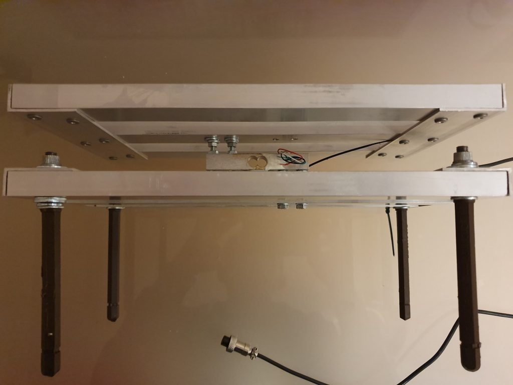
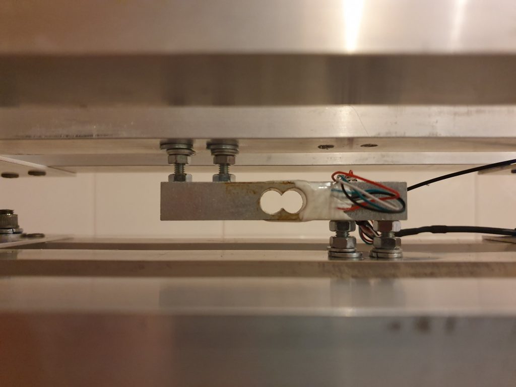
The aluminum elements are held together by steel rivets. The lower plate is used as a support base for the balance while the upper plate is used to support the load to be measured. The load cell is inserted in a “sandwitch” between two plates and anchored to the central bars of the lower plate at one end and the upper plate at the other end:

The following figure shows the balance in its final assembly:
References
[1] HX711 datasheet

1 Reply to “Building an electronic weight scale using a load cell sensor”