Abstract
A Direct Current Uninterruptible Power Supply system is a special version of UPS providing a regulated DC output to power typical low/medium-power DC devices.
The DC UPS described in this article is using a lithium battery pack as backup energy storage and is powered by a 150W 24V DC switching power supply. It provides regulated DC outputs for 5V, 12V and 19V devices.
The backup battery pack is composed by five lithium iron phosphate (LiFePo4) batteries connected in series providing a nominal voltage of 16V (3.2V x 5). The battery model adopted in this project has 32700 form factor (32mm diameter x 70mm height) rated for 7ah capacity. As a consequence, the global power capacity (see ref. [1]) of the battery pack is 112Wh. This is about 15% than a traditional AC UPS in the same range of output power equipped with a typical 12v/7ah lead acid battery corresponding to 96Wh. Furthermore, the power density of lithium batteries is increasing over the time and you can easily find same form factor batteries rated for 12800mah that in the same configuration would be able to provide the outstanding power of 204Wh!
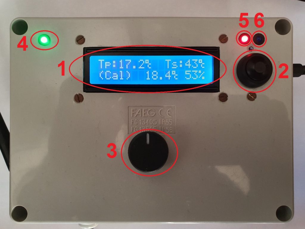
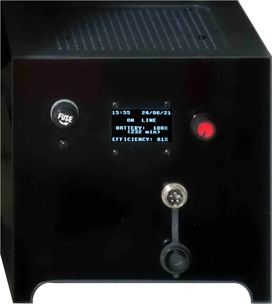
Here follows a picture (front view) of the assembled UPS. The front side of the case hosts an OLED display, a knob driving a rotary encoder/button, the connector to update the firmware and the battery fuse.
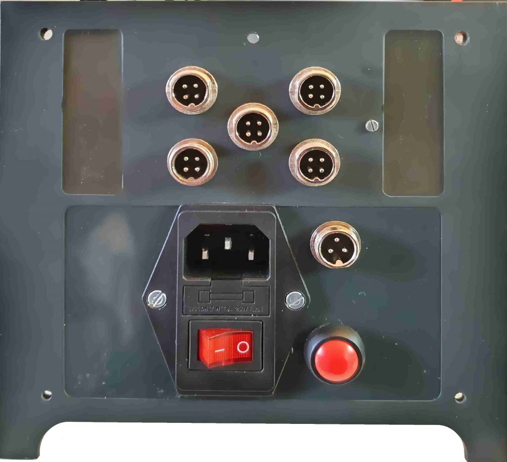
The back side of the UPS includes the 220V plug with the power switch, a button to start the UPS when on battery, the serial/USB interface to connect the UPS to the PC or any other client device supporting the APC® UPS-Link protocol (a NAS for example) and obviously the DC power outlets.
Principle of operation
The DC UPS is intended for use with typical low/medium power DC devices like routers, mini pc, monitor, NAS and so on. Differently from a typical AC UPS, that provides an uninterruptible alternate current output, the DC UPS provides a direct current output with different voltage levels as required by connected DC devices. This way, the UPS can be used to power the devices directly replacing the power rectifiers normally used when the devices are connected to the AC plug.
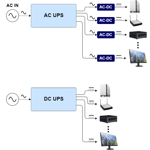
Other than the topology simplification, the AC-UPS and the DC-UPS differ for the number of power conversions being implemented between the AC in plug and the output device. Following picture shows the block diagram of a typical line interactive AC UPS:
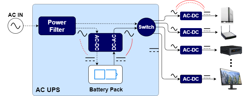
Dotted lines represent the connections when the UPS is working on line, while solid lines represent the connections when the UPS is working on batteries. Similarly, red lines highlight the power conversions from AC to DC (rectifiers) and from DC to AC (inverters) in the two cases. As you can see on the diagram, this UPS requires two conversions when on-line, the first one needed to charge the battery (AC-DC rectifier) and the second one needed to convert the UPS output AC power to DC power as required by connected devices (each device having its own power adapter). When the UPS is on batteries you still have two power conversions. The first one from battery DC power to UPS AC output (inverter) and then again the AC to DC conversion by the device power adapters. Nevertheless, the typical output waveform generated these budget UPS is not a pure sine waveform but it more like a square waveform that can be seen as a sine waveform plus a lot of low to high frequencies harmonics representing output noise.
Let’s now have a look to the block diagram of the DC UPS:
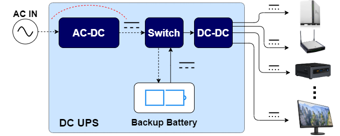
The topology is quite simpler since it eliminated the need of the inverter and the device power adapters. When working on line you just have one AC to DC power conversion being implemented by the internal SMPS. This generates the stable DC output to charge the battery, and to power the output devices. You only need some additional high efficiency DC to DC regulators (buck/boost converters) to generate the right DC voltage for each device. When working on batteries, there will be no AC/DC or DC/AC conversion in place. The extremely stable battery output will be used to power the output devices.
There are some advantages in using a DC UPS instead of a typical AC UPS, for example:
- Efficiency:
- The DC UPS requires less power conversions than the AC UPS thus reducing the power loss in each conversion.
- One high power, high efficiency SMPS powering all the devices instead of multiple smaller SMPS one for each device. Using one bigger and well-engineered SMPS will allow a better efficiency than using multiple smaller and cheaper power adapters.
- Battery duration: this is strictly connected to the previous point, considering that when the UPS is on battery only DC-DC power regulators will be working between the battery and the output devices.
- Space and cabling under the desk.
Solution description
The DC UPS block diagram is the following:
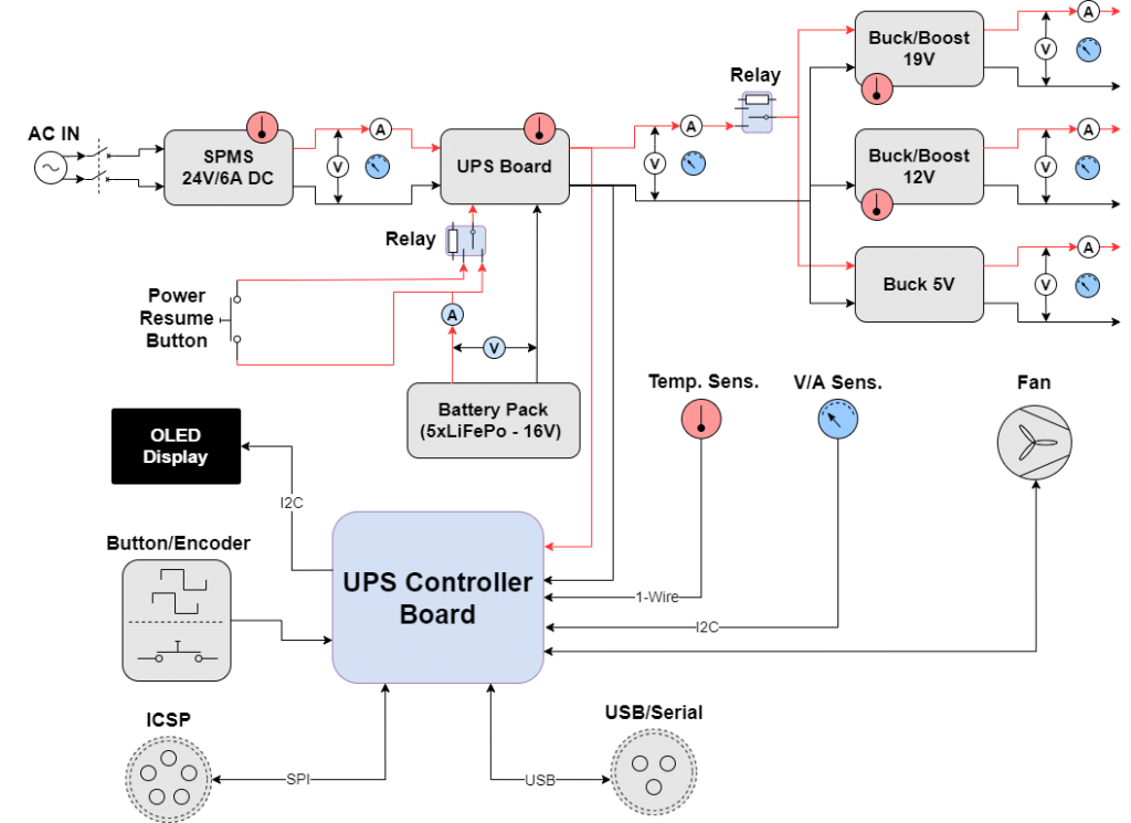
The AC line is connected to a 24V/6A Swithing Mode Power Supply. The MeanWell LSR 150-24 (see ref. [2]) has been used in this project due to the power provided in a small space. The MeanWell SMPS has a very good efficiency close to 90% and a low profile on only 30mm height.
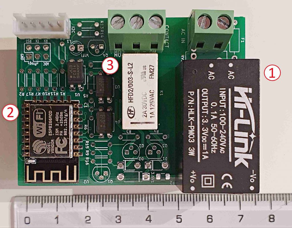
The output of the SMPS is used to power the DC UPS board (UPS-0528-11 – see ref. [3]). The UPS board is shown in the following picture:
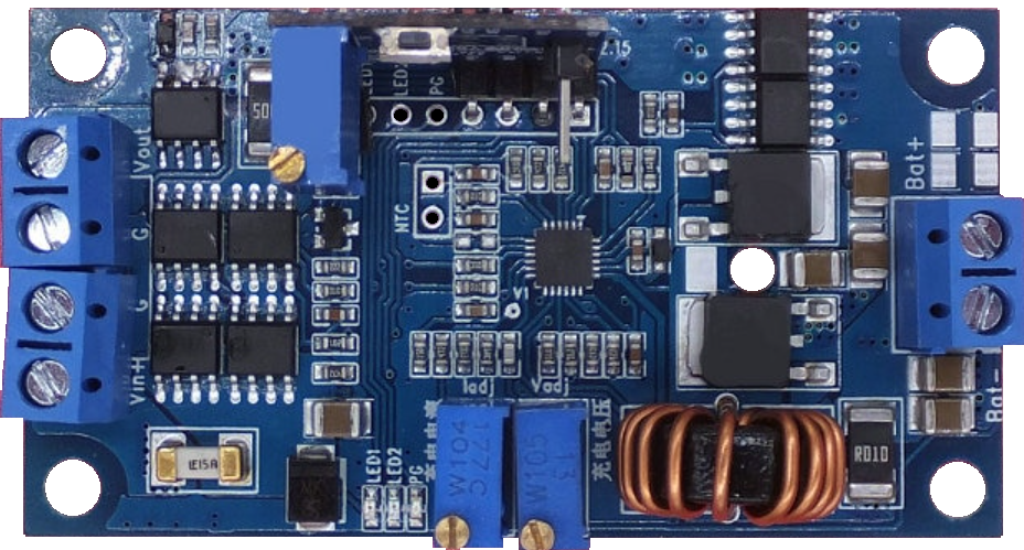
The board is a well-engineered PCB can be found as a preassembled module from different suppliers at a cost between 15 and 20 Euro and delivery from China. Here are the most relevant features:
- Maximum input current 15A (output current + battery charging current)
- Unregulated output voltage: this is the input voltage during normal operation or the battery voltage when the input power is missing
- High efficiency charging with synchronous Step-Down adjustable regulation: both lead acid and lithium batteries are supported
- Three stage charging: constant current, constant voltage and floating charging
- Charging cut-off and time limited charging time (after 10 hours of continuous charging – configurable)
- Minimum power consumption of only 30mA with no load
The backup power storage (backup battery) used for this project is self-made and is based on 5×32700 lithium iron phosphate (LiFePo4) batteries connected in series and packed together. Consequently, the nominal voltage of the battery pack is 16V (5×3.2V) while the limit charging voltage is 18V (5×3.6V). Maximum charging voltage has been limited to 17.3V in this project to preserve battery life while paying a negligible inefficiency in battery capacity. In fact, a typical LiFePo battery gets charged to 99% of its capacity when the charging voltage is between 3.4V and 3.5V that corresponds to something between 17V and 17.5V for our battery pack (see refs. [4] and [5]).
To avoid the batteries to get unbalanced over the time, I have also included a protection module with balancing capability directly into the battery pack. The connection schema between the protection module and the batteries is shown below:
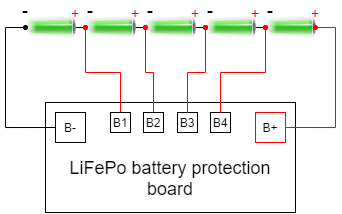
The protection module has the following features:
- Designed for Lithium Polymer batteries: 3.6-3.7V single cell nominal voltage
- Single cell battery overcharge protection limit: 4.21-4.29 V
- Single cell battery over-discharge protection limit: 2.72-2.88 V
- Over discharge protection current limit: 100A
- Over temperature protection
- Shortage protection with 100-600 uS delay
- Maximum discharge current: 60A
- Single cell balancing function (60mA charge/discharge balancing current)
The battery pack is connected to the UPS providing the backup power in case of input DC power outage. The UPS board output is not regulated, being the input DC voltage (24V) when on-line and the battery voltage (15-18V) when on battery. The UPS board only ensures that switching between DC input and battery input happens seamlessly in case the power outage. UPS board output is regulated to match the output voltage requirements of the connected devices using buck/boost DC to DC converters. The DC UPS provides three different DC outlets with the following characteristics:
- Five multiple voltage outlets. Each outlet has four pins. One pin is used for ground the other pins are used to provide different output voltages. This way you can select the output voltage for each outlet just switching the cable. Available output voltages are:
- 19V/8A
- 12V/8A
- 5V/3A
The 19V output requires an automatic buck/boost converter because the UPS board output is higher than 19V when on-line (24V) and lower than 19V when on battery (15-18V). The 12V output would require a buck converter because the UPS board output is always higher than 12V, similarly for the 5V output. Anyway, the same buck/boost converter is used both for 19V and 12V outputs in the latter case leaving the user the possibility to reconfigure the output voltage to a different (possibly higher) value, if necessary.
The buck/boost converter board used for 12V and 19V DC outputs in this project is very popular and in based on the LTC®3780 IC from Analog Devices (see ref. [6]) which is a high-performance automatic buck-boost switching regulator controller that operates from input voltages above, below or equal to the output voltage.
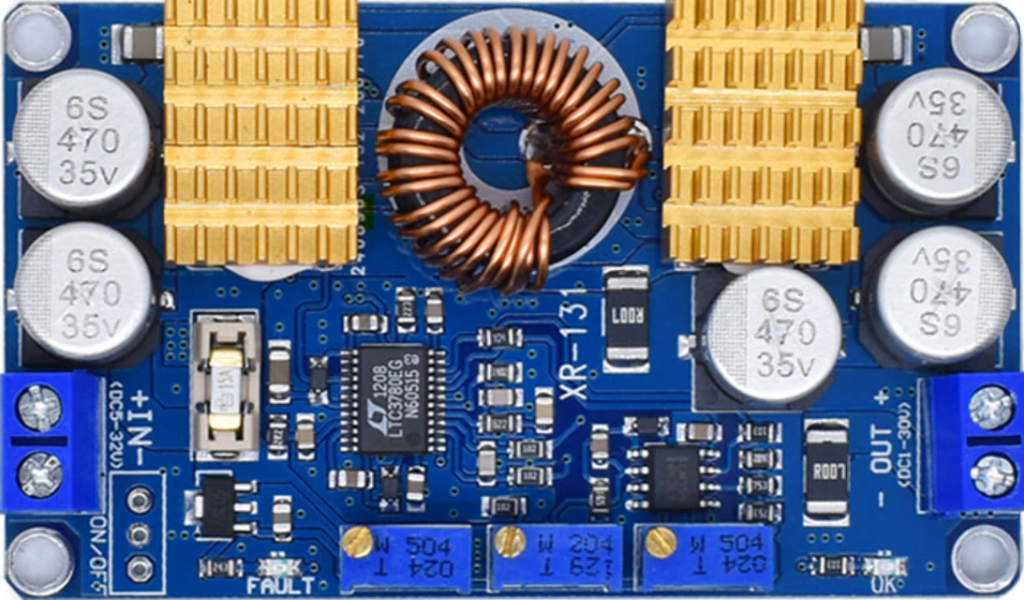
The converter has the following features (from datasheet):
- Single Inductor Architecture Allows VIN Above, Below or Equal to VOUT
- Wide VIN Range: 4V to 36V Operation
- Synchronous Rectification: Up to 98% Efficiency
- Current Mode Control
- +/-1% Output Voltage Accuracy: 0.8V < VOUT < 30V
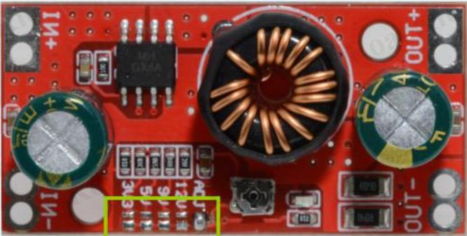
The buck converter for the 5V output is based on the MH-GX4A DC-DC 4A DC Step-Down regulator which is rated for 4A maximum output current (3A constant output) and a very highconversion efficiency from 24V to 5V that is around 95%. Again, the preassembled module is very cheap and can be easily found on the web.
The controller board is the core of the project and completes the design. The CPU is the Low-power Atmel® AVR® 8-bit Microcontroller ATmega644p (see ref. [7]). The board includes several external components used to monitor and adjust the UPS operating parameters. The controller board block schema is depicted below:
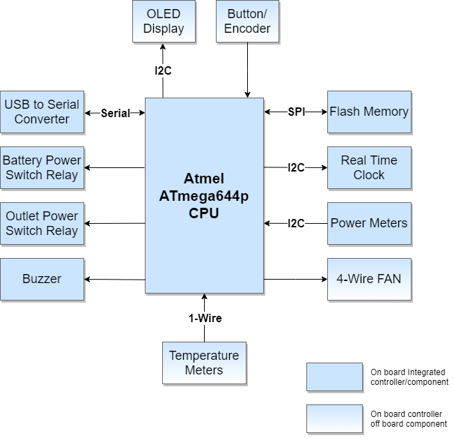
Details for the diagram components are listed below:
- Power Meters: these are 6 x I2C INA219A voltage/current sensors (ref. [8]) corresponding to V/A markings on the connection wires in the UPS block diagram (Fig. 6)
- 4-Wire Fan: this is the fan controller circuit. Fan connection includes both tachymeter and pwm pins respectively to measure and control the fan speed
- Battery Power Switch Relay: latching power relay (see ref. [9]) driver circuit. This is used to connect/disconnect the battery pack from the UPS board.
- DC Out Power Switch Relay: latching relay driver circuit. This is to connect/disconnect power for UPS DC outlets. The relay is the same model used for the battery power switch.
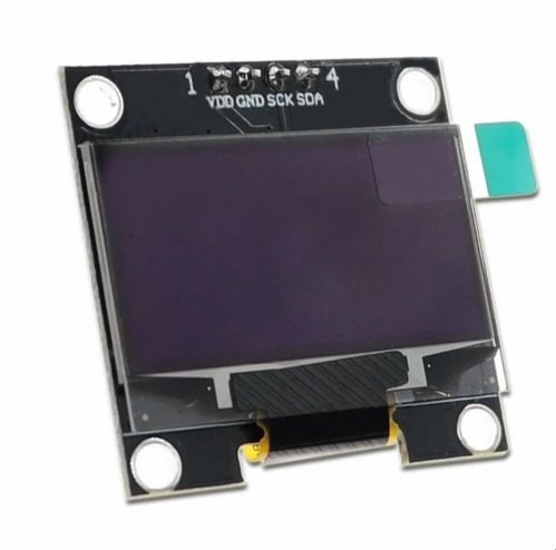
- OLED Display: This is an I2C 128×64 monochrome display
- Flash Memory: 64Mbit SPI Flash Memory (see ref. [10]) used for UPS data logging
- Real Time Clock: provides a real time date/time reference to controller board. This is based on the DS3231MZ IC (ref. [11]) and is equipped with a backup battery (CR2032) to keep time when the UPS is shut down
- Temperature Meters: 1-Wire protocol interface for a chain of 6 x DS18B20 temperature sensors IC (see ref. [12]).
- Button/Encoder: interface for button / rotary encoder controller circuit. This is used to allow the user to interact with the UPS.
- USB to Serial Converter: USB interface for UPS state monitoring compatible with APC monitoring protocol
- Buzzer: a passive buzzer used to send audible alerts to the user when the UPS reaches the low battery condition or in case of critical failures.
Power meters allow the controller software to monitor the global power balance of the UPS and the health status of the DC-DC converters. Sensing both current and voltage enables the software to calculate the total power drain from external devices on the 5V, 12V and 19V outlets. Similarly, power meters located at the UPS board input, output and battery connection can be used to understand whether the UPS is running on batteries or is online and the corresponding power drain from the battery pack or the input power supply. In addition, the control software can monitor if the outlet voltage goes out of the acceptable tolerance and decide to disconnect the output power to protect the external devices. Battery voltage is also used to estimate the state of charge of the battery and, when running on battery, can be used in conjunction with the power drain to calculate the residual life time of the battery. When the residual battery time is below a configured threshold, the UPS starts beeping the buzzer to advice the user to save the current work before the UPS initiates the self-switch off sequence.
The UPS electronic components are mounted on a square iron stand. Components are located on both front and back side of the stand, as shown in the following pictures:
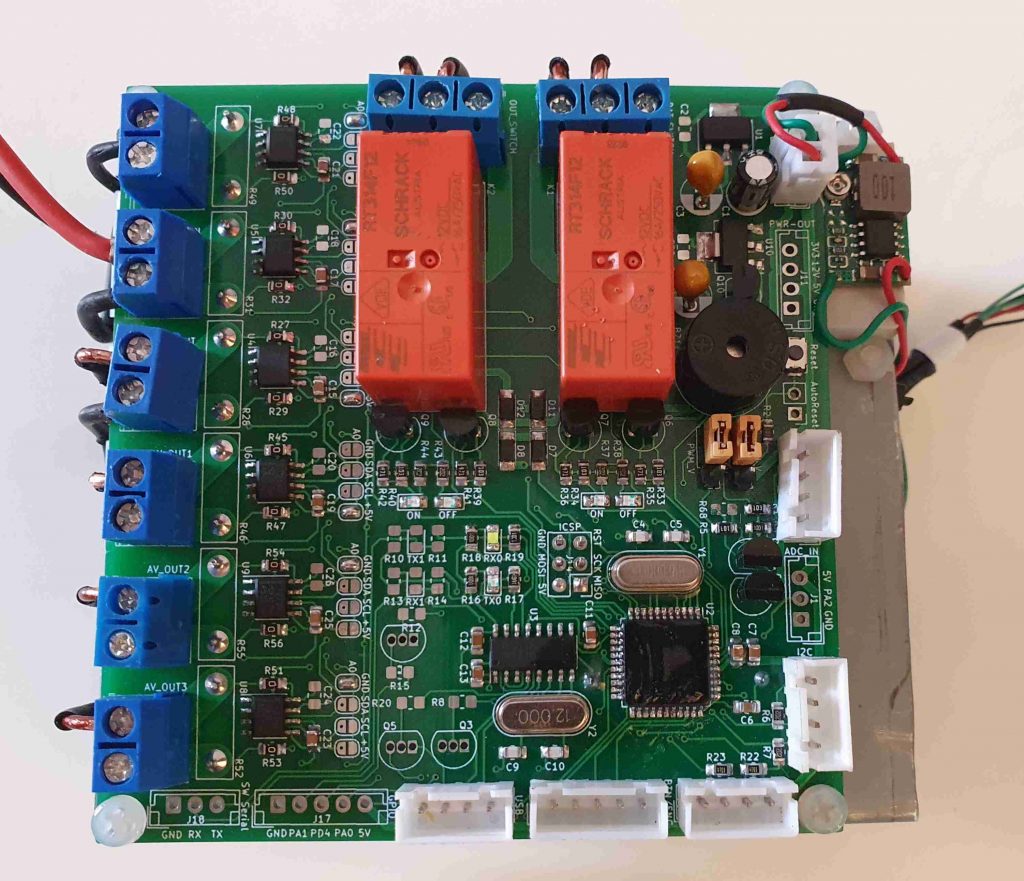
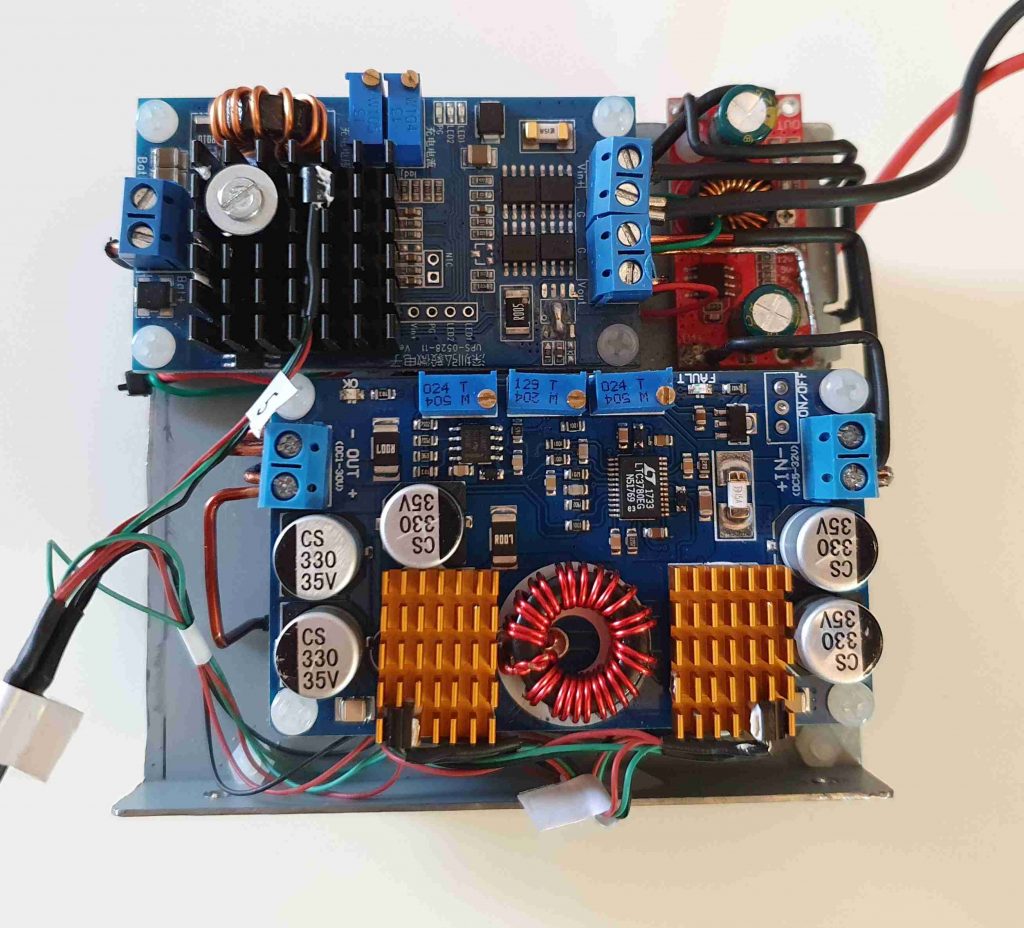
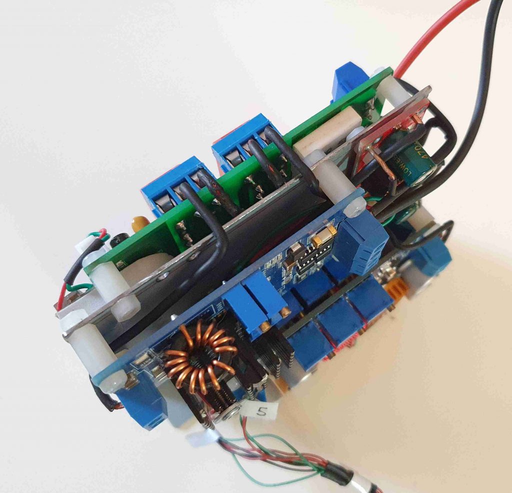
The PCB is mounted on a iron stand which hosts the rest of the components (DC-DC regulators) on the back side, as shown by the following pictures:
The housing box of the UPS hosts the SMPS regulator and the UPS electronics as shown in the following picture:
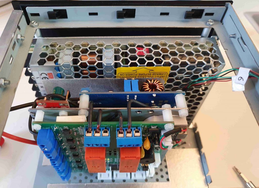
The remaining space within the box hosts the battery pack. The front cover of the box hosts the display, the button/encoder, the ICSP programming interface, the back side of the box hosts the DC outlets, the AC input plug, the USB serial interface and the emergency start button (to force restart the UPS on battery). Finally, a low profile cooling fan is mounted just below the lid of the box.
DC UPS Control Software
Other than monitoring the health status of the UPS, the control software is also able to emulate the Smart APC Protocol (see. refs. [13], [14], [15], [16]). In order to use this feature, the device must run the APC monitoring software. In case of a PC, the monitoring software is PowerChute Business Edition (see ref. [17]). The monitoring device must be connected to the UPS using the USB connector located on the back side of the UPS. The USB port is used to emulate a serial port and is operated by the CH340G usb to serial converter (see ref. [18]). Prior to installing the APC software, the CH340G drivers must be installed on the monitoring device (see ref. [19]).
The protocol emulator implements a subset of the APC protocol commands that include both inquiry and configuration commands. When a configuration parameter is changed, the emulation software persists the updated configuration to a permanent storage area (see “Using APC PowerChute management software with DC UPS” section below for more details).
The UPS has an integrated logging service to log events and metrics during operation. Log records are persisted to an external flash storage of 8 Mb (64 mbit) organazed in 2048 pages of 4 Kb each. The logger service stores the records sequentially into the flash storage rolling over the pages when the storage is full.
Log records are quite simple and contain the timestamp, the severity and a short message describing the event. Typical log events include the change of state from “on line” to “on battery” and the “low battery” condition. The timestamp is kept updated by the external RTC clock circuit that includes a small lithium backup battery to hold the time even when the UPS is shut down (both external AC and battery disconnected).
The UPS controller board includes a 1-wire interface to connect a daisy chain of temperature sensors based on the well-known DS18B20 IC. There are six temperature sensors measuring:
- The SMPS power supply temperature
- The buck/boost DC-DC regulators temperature (2 sensors each placed on the heat sinks – see figure 9)
- The UPS board temperature
The controller board software sample the temperature every 10 seconds and calculates the maximum temperature between the monitored components. This is used to regulate the cooling fan speed which is placed just below the upper lid of the case. The target rotation speed in RPM of the fan is a linear function of the maximum temperature.
The algorithm controlling the fan speed is adaptative. Fan interface includes both the speed control line and a tachymeter line to sense the fan rotation speed. The fan speed is regulated by the control software varying the duty cycle of a square wave sent on the speed control line. The square wave must have a fixed frequency that is supposed to be between 25 ad 35Khz to avoid generating audible noise. The actual speed of the fan is sensed through the tachymeter input line and used to adjust the duty cycle in order to reach the target rotation speed. The fan control software implements a closed loop system (see ref. [20]) based on negative feedback control (see ref. [21]) strategy.
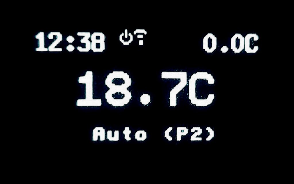
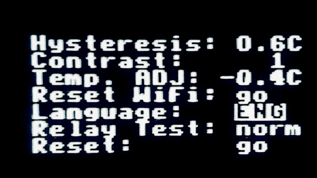
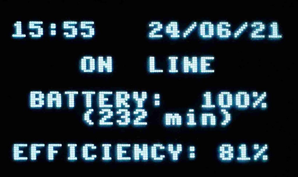
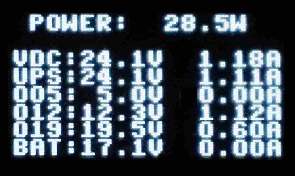
The last element of the design is the I/O subsystem which includes an 128×64 matrix OLED display (see ref. [22]) based on the well-known SSD1306 driver IC (see ref. [23]) and a rotary encoder with a button. Display is used to show the operating parameters of the UPS like the status, the battery level, the total efficiency, the output voltage, current and power and the system logs. Using the encoder and the integrated button, the user interacts with the UPS control software to browse different pages of the display, adjust the time or switch off the UPS.
Following picture shows sample pages of the UPS display:
Using APC PowerChute management software with DC UPS
As briefly introduced above, the UPS control software is able to emulate the APC® UPS-Link protocol to provide information about UPS status, the battery level, the estimated remaing runtime remaining when on battery and so on. On a Linux or Windows PC connected to the UPS the utility understanding the UPS-Link protocol is PowerChute Business Edition. This utility, installs a background agent running on the PC that communicates with the UPS and can be configured to execute the proper actions when the UPS is on battery or is low of battery. Examples of these actions include running a custom command or/and hibernate/shutdown the PC. The UPS Link protocol is a serial protocol running at 2400 bps. As shown in figure 2, on the back side of the DC UPS there is a USB connector. This is a serial over USB channel handled by the CH340G processor. After installing the proper drivers on the client device, the USB connection is recognized as a standard COM serial port on the client device.
During the installation process PowerChute Business Edition (PBE) requires the user to set the target UPS model. To make sure the PBE agent will use the UPS Link protocol, a possibility is to select “Other type B” as UPS model and the COM interface corresponding to the UPS connection as serial port. The software will install an agent that, on a Windows machine corresponds to a service named “APC PBE agent”. The service will be shown in the Windows service list dialog with the following name and description:

The agent has a web interface that can be accessed at the following URL:
If the agent is running, the following login screen should appear:

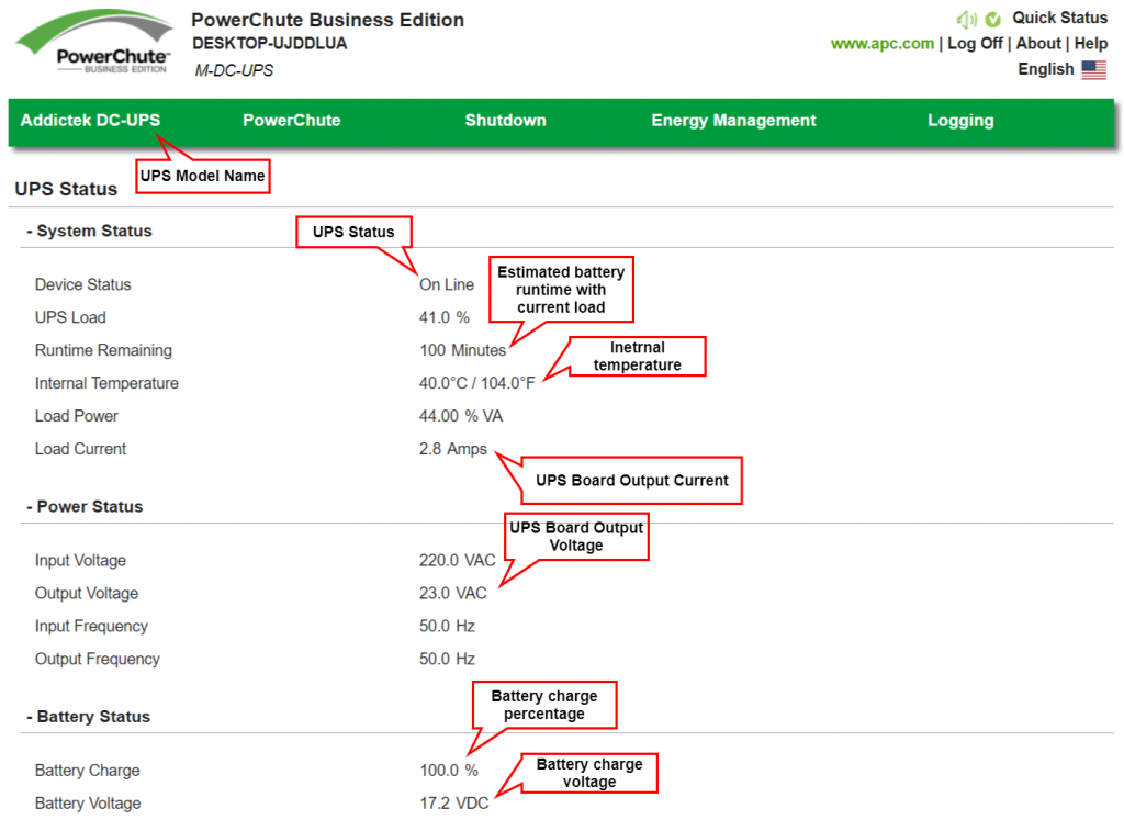
After logging in with the credential entered during the installation process, if the connection between the agent and UPS is ok, the main page will display UPS properties, like the following:
The rest of the pages allow the user to configure the agent behavior, like the shutdown process when the UPS gets on battery/low battery.
References
@battery_power{battery_power,
author="Lady Ada - Adafruit Industries",
title = "{Power Capacity and Power Capability}",
year = "Jun 25, 2021"
}@mw_lsr_150_24{mw_lsr_150_24,
author = "MeanWell",
title = "{LSR-150-24 - 150W Single Output Switching Power Supply}",
year = "2021"
}@ups_0528_11{ups_0528_11,
author = "Unknown",
title = "High Power DC UPS Module}[Bibtex]
@lifepo4_1{lifepo4_1,
author = "PowerStream",
title = "{How does capacity correlate with charge voltage for lithium iron phosphate batteries?}",
year = "Apr 23, 2021"
}[Bibtex]
@lifepo4_2{lifepo4_2,
author = "PowerStream",
title = "{How to charge Lithium Iron Phosphate Rechargeable Lithium Ion Batteries}",
year = "Jul 31, 2019"
}[Bibtex]
@ltc3780{ltc3780,
author = "Analog Devices",
title = "{LTC3780 - High Efficiency, Synchronous, 4-Switch Buck-Boost Controller}",
year = "Feb 2019 - Rev. G"
}[Bibtex]
@atmega644p{atmega644p,
author = "Atmel Corporation",
title = "{ATmega644P - 8-bit AVR Microcontroller with 64K Bytes In-System Programmable Flash}",
year = "2015"
}[Bibtex]
@ina219a{ina219a,
author = "Texas Instruments",
title = "{INA219 Zerø-Drift, Bidirectional Current/Power Monitor With I2C Interface}",
year = "Aug 2008 – Rev. Dec. 2015"
}@rt314f12{rt314f12,
author = "Schrack",
title = "{16A Bistable Power PCB Relay}",
year = "Aug 2019, Rev. 0819"
}[Bibtex]
@w25q64fv{w25q64fv,
author = "Winbond",
title = "{W25Q64FV - 3V 64M-BIT SERIAL FLASH MEMORY WITH DUAL/QUAD SPI & QPI}",
year = "Jul 18, Rev. S"
}[Bibtex]
@ds3231mz{ds3231mz,
author = "Maxim Integrated",
title = "{DS3231 - Extremely Accurate I2C-Integrated RTC/TCXO/Crystal}",
year = "19-5170; Rev 10; 3/15"
}[Bibtex]
@ds18b20{ds18b20,
author="Maxim Integrated",
title = "{Programmable Resolution 1-Wire Digital Thermometer}",
year = "19-7487; Rev 6; 7/19"
}[Bibtex]
@apc_smart_protocol{apc_smart_protocol,
author = "Schneider-Electric",
title = "{APC by Schneider Electric UPS-Link Communications Protocol Specification}",
year = "2019"
}@apc_smart_protocol_1{apc_smart_protocol_1,
author="Network UPS Tools",
title = "{APC’s smart protocol}",
year = "Sep. 2016"
}@apc_smart_protocol_2{apc_smart_protocol_2,
author="Kiryl Bahdanau",
title = "{Unofficial APC UPS protocol}",
year = "Feb. 2020"
}@apc_smart_protocol_3{apc_smart_protocol_3,
author="Various",
title = "{APC’s smart protocol}",
year = "Feb. 2000"
}@apc_powerchute_be{apc_powerchute_be,
author="Schneider-Electric",
title = "{APC - PowerChute Business Edition}",
year = "v10.0.2 - 2021"
}[Bibtex]
@ch340g{ch340g,
author="Nanjing Qinheng Microelectronics Co., Ltd.",
title = "{CH340 - USB to UART Bridge Controller}",
year = "N/A"
}@ch340g_drivers{ch340g_drivers,
author="Nanjing Qinheng Microelectronics Co., Ltd.",
title = "{CH340 - Drivers Download}",
year = "N/A"
}@closed_loop_systems_1{closed_loop_systems_1,
author="Electronics Tutorials",
title = "{Closed-loop Systems}",
year = "Jan. 2019"
}@negative_feedback_systems_1{negative_feedback_systems_1,
author="Electronics Tutorials",
title = "{Negative Feedback Systems}",
year = "Sep. 2019"
}@oled128x64{oled128x64,
author="Vishay",
title = "{I2C 128x64 Graphic OLED Display}",
year = "Sep. 2019"
}[Bibtex]
@ssd1306{ssd1306,
author="Solomon Systech",
title = "{128x64, Dot Matrix OLED/PLED Segment/Common Driver with Controller}",
year = "Sep. 2019"
}